
- Home
- >
- Products >
- Programmable High low temperature test chamber >
- Programmable high and low temperature testing machine
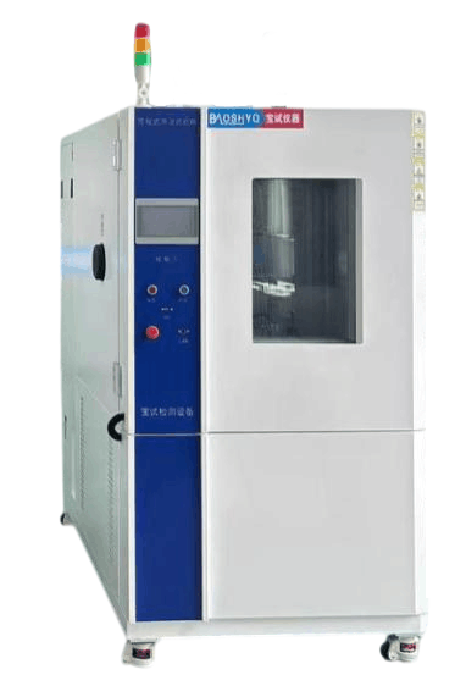
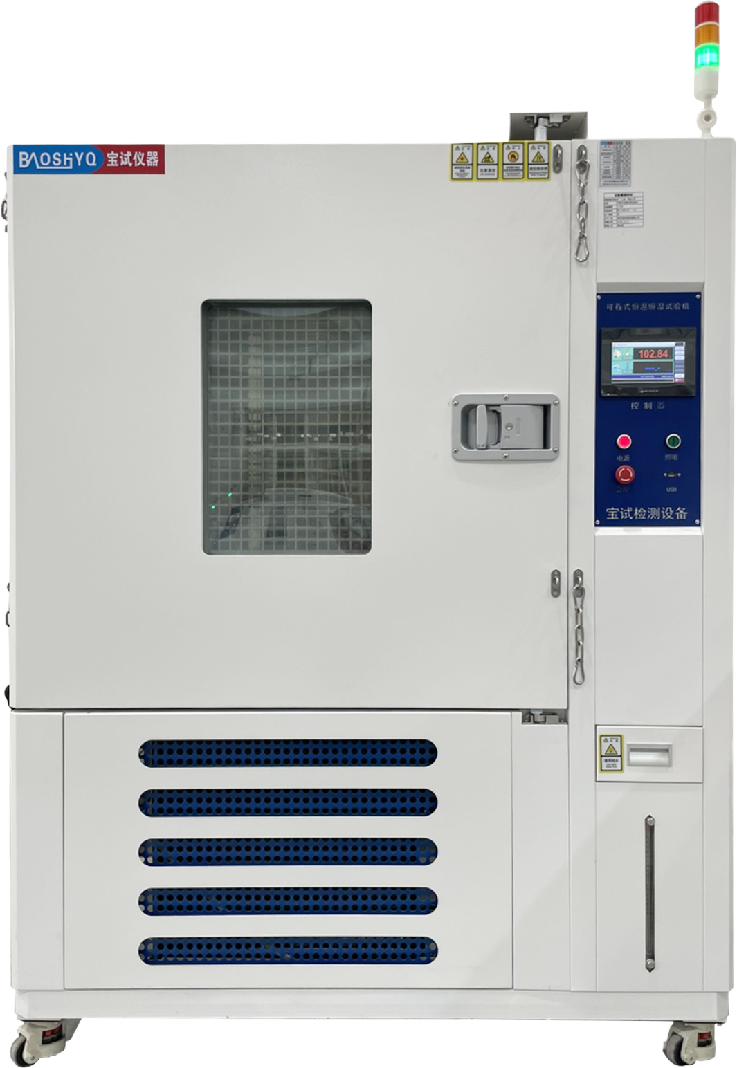
BS-HLC-408L
he Programmable High and Low Temperature Testing Machine belongs to the category of macro-climate simulation equipment. It is suitable for assessing the temperature aging tests of electrical and electronic products, including those in the new energy, automotive, household appliances, semiconductor, electronics, aerospace, universities, and instrumentation components industries. It is also applicable for adaptability tests under high-temperature, low-temperature, and high-low temperature alternating environmental conditions. Email
I. Technical Parameters
| Serial Number | Project Name | Technical Specifications |
|---|---|---|
| 1.1 | Equipment Name | Programmable High and Low Temperature Testing Machine |
| 1.2 | Equipment Introduction | The Programmable High and Low Temperature Testing Machine belongs to macro-climate simulation environmental equipment. It is applicable for the temperature aging tests of electrical and electronic products in industries such as new energy, automotive, household appliances, semiconductors, electronics, aerospace, universities, and instrumentation components, as well as adaptability tests under high-temperature, low-temperature, and high-low temperature alternating environmental conditions. |
| 1.3 | Equipment Model | BS-408DD |
| 1.4 | Effective Volume | 408L |
| 1.5 | Inner Chamber Dimensions | 800850600 (WHD) (mm) |
| 1.6 | Outer Chamber Dimensions | |
|
Front - back structure: approximately 105016801550 (WHD) (mm) Left - right structure: approximately 95016801050 (WHD) (mm) (Subject to the final confirmed 3D drawings) |
||
| 1.7 | Temperature Range | -40℃~150℃ |
| 1.8 | Heating Rate | -40℃ ~ 150℃ ≥3℃/min (non-linear throughout the process, acceptance under no-load condition) |
| 1.9 | Cooling Rate | 150℃ ~ -40℃ ≥1℃/min (non-linear throughout the process, acceptance under no-load condition) |
| 1.10 | Temperature Display Accuracy | 0.01℃ |
| 1.11 | Temperature Deviation | ±2℃ |
| 1.12 | Temperature Fluctuation | ≤±0.5℃ |
| 1.13 | Temperature Uniformity | ≤2℃ |
| 1.14 | Cooling Method | Air Cooling |
| 1.15 | Equipment Weight | 350KG |
| 1.16 | Equipment Power | 380V, 7.5KW |
| 1.17 | Others |
-
The above performance indicators are measured under the conditions of no load, no test materials, and an ambient temperature of 25±2℃.
2. 70dB (measured 1 meter away from the chamber door at a height of 1.5 meters) |
II. Testing Standards Compliance
| Serial Number | Test Item | Standard Description |
|---|---|---|
| 2.1 | General Standards | |
|
GB/T 2423.2 - 2008 - Test Method: High Temperature GB/T 2423.1 - 2008 - Test Method: Low Temperature GJB150.4A-2009 - Low Temperature Test Method GJB150.3A - 2009 - High Temperature Test Method GBT 2424.6 - 2006 - Environmental Testing for Electrical and Electronic Products - Performance Verification of Temperature Test Chambers GBT 2424.5 - 2006 - Environmental Testing for Electrical and Electronic Products - Performance Verification of Temperature Test Chambers |
||
| 2.2 | Acceptance Execution Standards | |
|
Manufacturing standards: GB/T10586 - 2006, GB/T10592 - 2008 Verification standards: GB/T5170.2 - 2017, GB/T5170.5 - 2016 Technical standards: Accepted according to the signed technical index requirements |
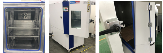
III. Equipment Structure
| Serial Number | Project Name | Technical Specifications |
|---|---|---|
| 3.1 | Chamber Structure | Integrated (left - right/front - back) frame structure, welded with national standard channel steel. The equipment is sturdy and durable, with low vibration and noise during operation, ensuring overall reliability and safety. |
| 3.2 | Inner Chamber Material | Made of 1.0mm thick SUS #304 stainless steel; fully welded to ensure the sealing performance of the inner chamber. The bottom is reinforced to bear an average load of ≥300KG. |
| 3.3 | Outer Chamber Material | Made of 1.2MM thick cold - rolled steel plate, double - sided sprayed, in blue and white color. (Customizable according to customer requirements, color swatches or color numbers can be provided) |
| 3.4 | Insulation Material | The insulation layer is 100MM thick, made of fire - resistant, high - strength rigid polyurethane foam insulation material, with a thermal insulation coefficient of less than 0.0212kcal/m∙hr. |
| 3.5 | Chamber Door Structure | Single - door. A double - layer silicone rubber sealing strip is used between the door and the chamber, which is resistant to high and low temperatures and anti - aging, ensuring sealing performance. An anti - condensation and anti - frost electric heating device is installed on the door frame and door edge to prevent condensate from forming on the chamber surface. |
| 3.6 | Test Observation Window | One vacuum multi - layer explosion - proof glass observation window is installed. The window has an anti - fog and anti - frost design: the periphery of the window is heated by film coating to prevent frost and water vapor condensation. A high - brightness energy - saving safety light is installed above the observation window (which can be manually turned on and off directly). |
| 3.7 | Airway Components | Equipped with a circulating fan, motor, extended aluminum shaft, and a multi - vane circulating fan with a structure resistant to high and low temperatures, achieving forced convection and vertical diffusion circulation. The air outlet is adjustable. |
| 3.8 | Sample Shelf | Made of stainless steel, with 2 sets of brackets, which can be adjusted up and down freely (customizable according to customer requirements). |
| 3.9 | Test Hole | One test hole with a diameter of 50mm is reserved on the left side of the chamber, and one set of silicone plug + sealing cover is provided. |
| 3.10 | Three - color Light | A three - color light is installed. Green indicates operation, yellow indicates stop, and red indicates failure. |
| 3.11 | Drainage Trough | There are drainage troughs around the inside of the chamber to facilitate the discharge of condensate and prevent internal water accumulation. |
| 3.12 | Pressure Balance Hole | A pressure balance hole is installed inside the chamber to balance the pressure inside and outside the chamber. |
| 3.13 | Universal Wheels | Universal wheels are installed at the bottom of the equipment to facilitate relocation, movement, and positioning. |
IV. Circulation System
| Serial Number | Project Name | Technical Specifications |
|---|---|---|
| 4.1 | Air Discharge Method | Forced internal circulation, with an air discharge mode of upper outlet and lower return. The guide vanes at the air outlet can disperse cold and hot air evenly and stably throughout the chamber. |
| 4.2 | Circulating Motor | Long - axis motor, with the main body placed outside the chamber, unaffected by the internal temperature and humidity of the chamber. The long shaft extends directly into the chamber, insulated and sealed with silicone. |
| 4.3 | Centrifugal Fan | Multi - vane centrifugal aluminum fan, which is lightweight, has a large air volume, high air pressure, is resistant to high and low temperatures, has a small expansion coefficient, and low operating noise. |
| 4.4 | Circulating Air Duct | The circulating air duct is matched with the refrigeration and heating systems. The sealing plate closely adheres to the evaporator and heating tubes, and the circulating air can fully carry away the cold and heat energy of the evaporator and heating tubes. |
| 4.5 | Sensor | Class A platinum resistance PT100+T temperature sensor, with stable operation and accurate detection. |
V. Refrigeration System
| Serial Number | Project Name | Technical Specifications |
|---|---|---|
| 5.1 | Refrigeration Method | Compression refrigeration |
| 5.2 | Compressor | Fully enclosed compressor from "Taikang", France |
| 5.3 | Evaporator | High - efficiency multi - stage finned evaporator with hydrophilic film (thickened fins) |
| 5.4 | Condenser | Shell - and - tube condenser (air - cooled) |
| 5.5 | Refrigerant | Non - fluorine environmentally friendly refrigerant R404A from DuPont, USA |
| 5.6 | Thermal Expansion Valve | Controls the opening of the expansion valve through the superheat degree of the gaseous refrigerant at the evaporator outlet |
| 5.7 | Oil Separator | Separates the refrigeration oil from the refrigerant, enabling each to perform its function |
| 5.8 | Drying Filter | The filter blocks solid particles such as iron filings, welding slag, and dirt to prevent blockages; the dryer absorbs moisture circulating with the refrigerant to prevent "ice blockage" inside the pipeline. |
| 5.9 | Solenoid Valve | Danfoss, roughly adjusts the refrigeration capacity of the entire refrigeration system |
| 5.10 | Leak Detection Method | The entire system pipeline is leak - tested by nitrogen pressurization for 24 hours. |
| 5.11 | Vibration Damping Design | The compressor chassis is isolated from vibration: the chassis has a waterproof design; the self - evaporating waterproof chassis effectively prevents condensate from flowing out. Moving parts such as the compressor and fan are vibration - isolated, designed for low noise. |
VI. Heating System
| Serial Number | Project Name | Technical Specifications |
|---|---|---|
| 6.1 | Heating Method | Driven by imported SSR (Solid State Relay), with contactless control, no noise, no electric arc, stable and reliable. |
| 6.2 | Heating Tube | Made of stainless steel finned nickel - chromium wire high - speed heater. |
| 6.3 | Heating System and Electrical Components | Completely independent system, without affecting the refrigeration and humidification systems. Temperature control is calculated by a microcomputer and automatically adjusted by PID. The output power changes according to the comparison result between the actual temperature value and the set value to achieve high precision, high efficiency, and high stability. Main low - voltage electrical components are all products of well - known brands: "Schneider" AC contactors, thermal overload relays, "OMRON" small intermediate relays, Delixi signal lights, switches, and circuit breakers, etc. |
VII. Control System
| Serial Number | Project Name | Technical Specifications |
|---|---|---|
| 7.1 | Control Method | Color touch screen + PLC control system |
| 7.2 | Screen Display | 7 - inch screen with a resolution of 800*480, 65535 true colors, LED backlight display. The set (SV) and actual (PV) values of temperature and humidity are directly displayed. It supports Chinese/English language switching display and true - color touch input. It can display the execution program number, segment number, remaining time, and number of cycles, as well as the running time. It also supports program editing and graphical curve display. |
| 7.3 | Set Temperature and Humidity | Can be set independently according to the test temperature range conditions |
| 7.4 | Data Recording | With a built - in recording program, the memory in the controller can store 3 months of 24 - hour operation data. It can automatically generate temperature and humidity curve files, data, operation records, alarm records, etc., and can present set values, actual values, number of cycles, temperature segments, temperature values, time, etc. in both numerical and graphical forms. |
| 7.5 | External Connections | Communication methods such as USB, RS485, and LAN ports are available, and it can be connected to a computer for full - function control, storage, printing, and recording. |
| 7.6 | Operation Modes | Fixed value/program/slope operation modes |
| 7.7 | Input Method | RT100×1 (dry bulb)/4~20mA are both built - in |
| 7.8 | Output Method | 12 points (temperature×1, END×1, RUN×1, T1~T4, TROUBLE×1, H1×1, TIME SIGNAL×3) |
| 7.9 | Display Accuracy | Temperature: 0.01℃, Time: 0.01 second |
| 7.10 | System Capacity | 1~120 test programs (i.e., can be divided into 120 program groups), with a maximum of 1~1200 steps (i.e., 1200 action steps), and a single - step time of 9999 hours and 59 minutes. |
| 7.11 | Login Method | Login with Chinese and English names/Chinese and English test names/display of running time |
| 7.12 | Deviation Correction | Prevents parameter deviations caused by various factors. After correction, the temperature and humidity values are more accurate and standard. |
| 7.13 | System Functions | Timing control, reservation control, power - off recovery, fault display |
| 7.14 | Password Control | Multiple layers of password protection can be set to prevent unauthorized use and modification of internal parameters by non - operators |
VIII. Safety Protection Devices
| Serial Number | Technical Specifications |
|---|---|
| 8.1 | High and low pressure protection for the compressor system |
| 8.2 | Overload, overcurrent, and over - temperature protection for the compressor |
| 8.3 | Oil shortage protection for the compressor |
| 8.4 | Overcurrent and over - temperature protection for the fan |
| 8.5 | Power supply phase loss, phase sequence error, phase imbalance protection, leakage protection |
| 8.6 | Ground protection for the test chamber shell |
| 8.7 | Independent over - temperature protection for the working chamber |
IX. Main Accessories List
| Serial Number | Accessory Name | Brand | Remarks |
|---|---|---|---|
| 9.1 | Control Instrument | Weishuo | |
| 9.2 | Compressor | Taikang, France | |
| 9.3 | Refrigerant (R404) | DuPont, USA | |
| 9.4 | Air - cooled Condenser | Customized by Baoshi | |
| 9.5 | Evaporator | Customized by Baoshi | |
| 9.6 | Expansion Valve | Danfoss, Denmark | |
| 9.7 | Capillary Tube | Daikin | |
| 9.8 | Oil Separator | Emerson, USA | |
| 9.9 | Solenoid Valve | CASTEL, Italy | |
| 9.10 | Drying Filter | Danfoss, Denmark | |
| 9.11 | Heating Tube | Finned nickel - chromium alloy electric heating tube (protected by a titanium tube shell) | |
| 9.12 | Over - temperature Protection Device | Rainbow, South Korea | |
| 9.13 | Switch | Delixi | |
| 9.14 | Contactor | Schneider | |
| 9.15 | Cable | Shangshang |
X. Installation and Use Conditions of the Testing Equipment
| Keywords | Specific Requirements |
|---|---|
| 10.1 Passage for Placement | The passage should allow the passage of the test chamber's external dimensions. Special attention should be paid to corners, door entry dimensions, elevator dimensions, etc. For installation sites on upper floors or underground spaces, the floor load - bearing capacity should be ≥500kg/m2. |
| 10.2 Floor Space and Surrounding Dimensions |
-
Space around the equipment: A: ≥60cm, B: ≥60cm, C: ≥ 80cm, D: ≥ 80cm
- The ground should be flat, with good ventilation, and free of flammable, explosive, and corrosive gases and dust. |
| 10.3 Other Requirements for the Test Chamber's Use Environment | -
Ambient temperature: 5~28℃ for optimal performance
- Humidity: ≤85%RH
- Air pressure: 86KPa~106KPa
- Electromagnetic environment: No strong vibrations and no strong electromagnetic radiation sources around the equipment
- Site drainage: A floor drain should be available within 2 meters of the test chamber |
| 10.4 Safe Storage Conditions for the Test Chamber | When the test chamber is not in use, the storage environment should always be >0℃. If the storage environment is <0℃, for water - cooled test chambers and humidity test chambers, all remaining water in the equipment should be drained in a timely manner to prevent pipes from being damaged by freezing. |
| 10.5 Voltage | Three - phase four - wire system, voltage: 380V±10%, 50HZ, power: 7.5KW |
| 10.6 Grounding Requirements | Ground resistance <4Ω, independent grounding, that is, TN - S grounding system, using a three - phase five - wire AC power supply (mixing the neutral and ground wires is strictly prohibited) |
XI. Related Service Commitments
| Serial Number | Project Name | Service Content |
|---|---|---|
| 11.1 | Equipment Warranty Period | The supplier provides a 1 - year warranty from the date of acceptance of the test equipment. During the warranty period, material costs, repair costs, etc. are waived (except for human - induced damage or natural disasters). The supplier promises to provide lifetime free technical support and conducts equipment |
Related Products
Copyright ----SUZHOUBAOSHI @2012---2035