|
3.1
|
Box Structure
|
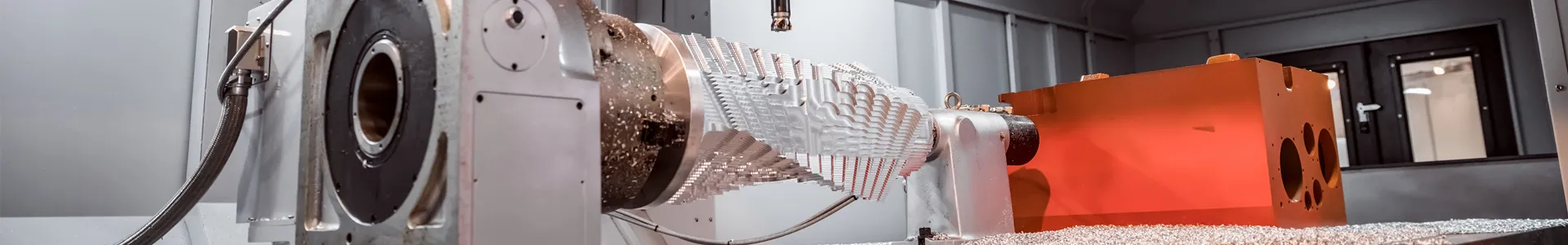
Integrated (left/right/front/rear) frame structure, welded with national standard channel steel. The equipment is sturdy and durable, featuring minimal operational vibration, low noise, and ensuring overall reliability and safety performance.
|
|
3.2
|
Inner Box Material
|
Made of 1.0mm thick SUS #304 stainless steel; fully welded as a whole to ensure the sealing performance of the inner box. The bottom is reinforced for a load-bearing capacity of ≥300KG average load.
|
|
3.3
|
Outer Box Material
|
Made of 1.2MM thick cold-rolled steel plate with double-sided spraying treatment, in blue-white color. (Customizable according to customer requirements, with color boards or color numbers provided)
|
|
3.4
|
Thermal Insulation Material
|
The thermal insulation layer is 100MM thick, made of fire-resistant high-strength rigid polyurethane foam thermal insulation material, with a thermal insulation coefficient of <0.0212 kcal/m∙hr.
|
|
3.5
|
Box Door Structure
|
Single-door design. A double-layer silicone rubber sealing strip is used between the door and the box, which is resistant to high and low temperatures and anti-aging to ensure sealing performance. The door frame and door edge are equipped with anti-condensation and anti-frost electric heating devices to prevent condensate on the box surface.
|
|
3.6
|
Test Observation Window
|
Equipped with 1 vacuum multi-layer explosion-proof glass viewing window, designed with anti-fog and anti-frost functions: the periphery of the viewing window uses film-coated heating for anti-frosting to prevent water vapor condensation. A safe high-brightness energy-saving lighting lamp is installed above the observation window (manually controlled by a direct switch).
|
|
3.7
|
Air Path Components
|
Adopts a circulating fan and motor, aluminum extended shaft, and a high/low temperature-resistant aluminum multi-wing circulating fan structure to achieve forced convection vertical diffusion circulation. Adjustable air outlet for the air inlet.
|
|
3.8
|
Sample Shelf
|
Made of stainless steel, equipped with 2 sets of brackets, which can be freely adjusted up and down (customizable according to customer requirements).
|
|
3.9
|
Test Hole
|
One test hole with a diameter of 50mm is reserved on the left side of the box, and one set of silicone plug + sealing cover is additionally provided.
|
|
3.10
|
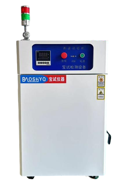
Three-Color Light
|
Installed three-color light: green for operation, yellow for stop, and red for fault.
|
|
3.11
|
Drainage Trough
|
Drainage troughs are provided around the box to facilitate the discharge of condensate and prevent internal water accumulation.
|
|
3.12
|
Balance Hole
|
A pressure balance hole is installed inside the box to balance the pressure inside and outside the box.
|
|
3.13
|
Universal Wheels
|
Universal wheels are installed at the bottom of the equipment to facilitate relocation, movement, and positioning.
|